

Introduction.
A new millennium, a new venue, a new SCRAP meeting.
This years meeting was held at the Clatterbridge Centre for Oncology in the Wirral, a beautiful part of the country and an excellent centre. This year, the theme was electrons, as there is renewed interest in the subject with increasing use of 3D planning systems and improvements to Monte Carlo calculations. However, talks also touched on ionisation chamber dosimetry for proton beams, and updating old programs.
Once again the meeting was well attended and supported - with chances for people to have discussions both formally and informally. We feel this is the strength of a group such as SCRAP, and we hope that it continues into the future.
The millennium may be new but our format was the same - six speakers followed by a round table session. The first talk focussed on the inputting of electron data into a planning system, with a few shortcuts to minimise the time involved.
Inputting electron data into Cadplan 3.1.3.
Kirsty Bryan-Jones and Tracy Soanes. Weston Park Hospital, Sheffield.
 Cadplan RTPS 3.1.3 uses the generalised gaussian pencil beam model for electron planning. It recommends separate treatment units
be set up for each electron energy and applicator combination (which would
mean a total of 25 units in their case!). This is a lot of work, but was
simplified by creating only 5 treatment units, one for each energy - after
comparing the input data for each applicator size and comparing isodose
distributions for 5 different applicator sizes with the same field set. There
were problems in calculating normalisation factors due to a variation in
dose, related to the selection of calculation area. Commissioning checks
were based on IPEM report 81.
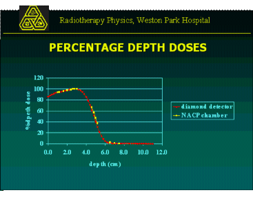
The DD curves were measured in a Wellhofer tank with a diamond detector, for open and blocked fields. The DD for blocked fields were normalised to open fields. Profiles measured to check the Cadplan model were Dmax, D80 and D50. These data were entered into the system.
The amount of data required was reduced to save time, and because electrons were infrequently used. When the DD curves for 5 applicators were compared they were virtually identical, with differences no more significant than those through repeatability problems selecting different calculation grids. So 1 treatment unit for each energy was used.
There were problems in choosing the grid size 1.25, 2.5, 5 or 10 mm) as 2.5 mm grid size takes 5 times as long as 5 mm. So a 5 mm grid size was chosen for commissioning. The grid placement was also found to affect the dose distribution. This was more significant at lower energies. This demonstrated the importance of calculating normalisation. The solution was to have the same grid area, though this gave difficulties in selecting the same grid twice. MU calculations were done using a simple manual system, as applicators are not in separate treatment units.
The data was verified against measured data, using IPSM guidelines - with numerous checks planned, electron cutouts, extended SSD etc. The depth dose data agreed within 2 mm for a 6x6 applicator and within 1 mm for all other applicators, while measured doses agree with Cadplan. Other checks have just been started. A possible solution to solve the inaccuracies in small field sizes is to create another treatment unit for the 6x6 applicator.
The second presentation, by Steve Locks from Newcastle, introduced a simple computer program which allowed thicknesses of build-up or shielding to be calculated for simple clinical electron treatments.
PC program to calculate doses through tissues in cases of electron backscatter from a lead interface.
Steve Locks. Newcastle General Hospital.
 In electron beam treatments of areas such as the pinna or lip, high Z materials such as lead are frequently used to shield underlying
structures. Without precautions backscattered electrons from this shielding
can lead to over dosage of tissue near to the interface. Alternatively, wax
bolus may be used to increase the dose at the surface of the treated area.
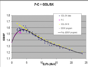
Klevenhagen and Lambert (K&L) determined experimental data on electron
backscattering - from 25MeV to 3MeV. More recent complimentary Monte-Carlo data have extended the range of data to lower energies (Perez-Calatayud et al (PC)). Recent data suggest as energy increases, backscatter
increases. It also shows a good comparison above 3MeV, but a significant
divergence between the P&C data and K&L below 3MeV - the area of
interest.
A PC program has been written to enable an interactive iterative search for the optimal combination of surface build up and thickness of wax between the lesion and lead to obtain as uniform a dose distribution as possible. This approach avoids complex hand calculations and interrogation of depth dose curves that can be time consuming and at risk of errors. It is spreadsheet based, with %DD data split up into bins of field sizes. Guesses are entered into the programs, and formulae return dose values at relevant points.
A few more guesses are added, with new results for comparisons. Once the user is happy the program provides a printout of thickness' (wax, lead etc.) required. It is a DOS based program, requiring look up files and data tables, but is very quick and easy to use. Of course checks are made that doses and thickness' are acceptable.
Monte Carlo modelling of electron beams for treatment planning.
Frank Verhaegen. Royal Marsden Hospital, Fulham Road.
 Treatment planning using a dose calculation algorithm based on Monte Carlo (MC) particle transport simulation techniques is
becoming feasible now that faster computers are more readily available and affordable. Frank's group is working towards
implementing MC dose calculation in the Dosigray treatment
planning system (TPS). Parallel processing on 10 PC's linked to the
Dosigray system is used to speed up calculations. MC techniques
can fully model electron scatter in the 3D structure of a patient,
including all heterogeneities and high atomic number materials as
well as lead shielding. Electron calculations are enhanced by using
a MC system because scatter is taken into account implicitly.
The physical characteristics of the Linac must be programmed into the system before calculations can be performed - including all cutouts and applicators. Scrapers on the applicators must be modelled accurately - including their composition - it was found that zinc gave a perfect match to the clinical measured data even though the linac manufacturer stated they were made from aluminium, lead or steel! Any model must be thoroughly verified against the measured beam data for all clinical situations. A model of a Varian 2100C linac at RMH was built, the so-called virtual linac, and verified against dose measurements in water. The model showed excellent agreement and was used to calculate output factors. Backscattered radiation from the jaws was determined from measurements and MC simulations.
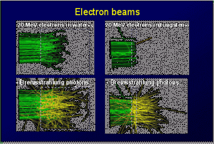
Once a virtual linac is fully tested and verified, it is then very easy to make other investigations into electron therapy without the need to make measurements. It is also possible to "do" things it would be impossible to do any other way - such as to track the paths of individual particles to see where they are scattered or absorbed.
To verifying whether the MC model could be used for other similar linacs, dose distributions and output factors for a recently commissioned 2100CD were calculated. Output factors at different SSD's were obtained. The new linac had significantly lower primary electron energies, but after re-tuning the model good agreement was obtained (2% of measured data). In fact an error in the measurements of the output factors was uncovered. It took 6 months to design the virtual Linac as there were many problems along the way. Now these have been overcome the process could be done much faster. The model can then be adapted for other Linac types and manufacturers. While Monte Carlo has proved a viable option for electron therapy using current hardware, albeit outside the realms of the basic radiotherapy department, photon calculations are still too slow to be a practical alternative to the present treatment planning systems.
Electron dose computation: a comparison of Helax TMS and Varian Cadplan.
Martin Clegg. Beatson Oncology Centre. Glasgow.
 The Beatson Oncology Centre is fortuitous in having both Helax TMS and Varian Cadplan treatment planning systems. The accuracy
of electron calculations of the systems have been tested by comparing isodose distributions and monitor unit values with
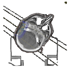
measurements. TMS is currently used to produce electron isodose distribution in head
and neck treatments. Treatments may use bolus to reduce cord dose, or involve oblique
incidence and the trachea.
To test the accuracy of calculations in these situations, measurements were made using TLD's at various depths and in off-axis positions in a solid water phantom. Shaped blocks of PMMA were used to reproduce surface bolus, and the trachea modelled using a 1.5 cm diameter air space.
Calibration against an ion chamber allowed the dose at the normalisation point to be determined and checked against monitor unit calculations. In general isodose distributions produced by both systems were accurate to within the ICRU definition. The TMS system however produced a 5mm positional error at the low dose side of the proximal penumbra for a 30-degree oblique field. Hot spot doses due to squared off bolus edges were overestimated by Cadplan and underestimated by TMS. Both planning systems underestimated dose downstream of the small air cavity by 10%. The accuracy of Cadplan monitor units was acceptable, while TMS underestimated for small fields by 8%.
In conclusion, calculations of relative dose were sufficiently accurate for clinical use, with the exception of those in the vicinity of small air cavities. Those near a step bolus must be interpreted with caution.
Ionisation chamber dosimetry for clinical proton beams.
Hugo Palmans. Ghent University, Belgium.
The advantages of radiotherapy using proton beams for certain clinical applications have brought about an increase in the number of proton therapy facilities in the last decade. The Bragg peak and the scattering properties of protons potentially allow a better location of dose deposition than can be achieved with conventional RT beams. The use of a modulating wheel can give a fairly homogenous distribution.
Reference dosimetry in a clinical proton beam is routinely performed using ionisation chambers, but few studies have been devoted to the study of the quantities required to determine absorbed dose to water in proton beams.
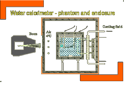
Historically dosimetry has been done with a calorimeter, a faraday cup or an ionisation chamber, following various codes of practice (AAPM 1986, ICRU 1999). Apart from the volume of the chamber, the three quantities needed for accurate dosimetry are the water to air stopping power ratio of the local charged particle spectrum, the average energy required to produce an ion pair in air and perturbation correction factors in the proton beam. Since 1979, several investigations have been published giving stopping power data and W-values. However, perturbation factors are assumed to be unity (water calibration compared with ionisation chambers showed factors smaller than 1-2%). MC studies were performed to evaluate the influence of perturbations of the primary and secondary fluence. This was confirmed with a recent study of 20 ionisation chambers.
Looking at the various codes of practice for proton therapy:
The ECHED COP stated Dw = Mcorr.Nk..Cp (conversion factor)
Whereas the IAEA stated DW,Q = MPcorr . ND,W,C .KQ,Q0
There was a discrepancy of 2.6% between the IPEM and ECHED W values.
Water calorimetry was used as an accurate method of determination, using the following equation.
DW = CW . TW + correction factors
A small thermister was needed to measure small temperature rises.
The conclusion drawn was that for proton dosimetry, the trend is towards Nd.w water calorimetry in a clinical proton beam.
Bringing EYEPLAN into the 21st Century.
Martin Sheen. Douglas Cyclotron Unit, Clatterbridge Centre for Oncology, Wirral.
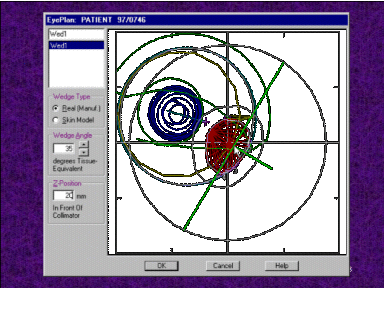 EYEPLAN is a specialised proton radiotherapy treatment-planning program for ocular tumours, and has been used to plan around
10,000 patients worldwide. It is written in FORTRAN on VAX machines, but this imposed restrictions on user friendliness and future
development. So Martin undertook the task I am sure a few of us have been faced with - bringing an old program up to date. The good
news from the talk was this is often not as hard as we may fear, and the improvements often more than justify the time spent. The
original program was written at MGH in 1983, and then used by PSI in
Switzerland and then Clatterbridge. It is now used in around 130 centres
worldwide. Upgrading to Visual Basic seemed a sensible idea, as it is
similar to C++, but the syntax is still similar to FORTRAN. Unfortunately
the original program contained 35,000 lines of code so it seemed daunting
at first.
Conventional 3D planning is image based with the patient in the treatment position. However when treating eyes there are limited options for beam entry as it is not desirable to treat through bone. Furthermore, if the eye moves, the scans become useless. The eye's small size adds to the difficulty. However, the eye has well defined, scalable geometry and even density. Object based code has many advantages as each area can be separately modelled (eye, eyelid etc).
The current system has obviously worked well enough - so why change at all? The current system is cumbersome, slow, and the user has to follow prescribed paths. The data transmission is slow, images can't be display and there are limits to what can be displayed. There were, of course, various options that could improve the situation: new hardware (expensive and only solves one problem), porting to the PC in FORTRAN (not cheap, fairly labour intensive and only solves a few problems) and converting to C++. The latter solves all the problems and is cheap - but a major effort is involved. In fact it was 6 months full time work. However, there were major advantages - in a better user interface, no more format statements, easy graphical printouts and so on. The result was a program with familiar operations but with greater ease of use. Faster calculations, decreased display times and the easy addition of future features also made it worthwhile.
The talk itself was very interesting and funny, and should give hope to all those faced with a similar task. One thing SCRAP tries to build on is the sharing of work being done, so that such effort does not have to be duplicated.
Round table discussion.
A lot of the round table discussion centred around the aspect of sharing software, particularly after the work done by Martin Sheen. So many people do work that would be useful in other departments - but there is little sharing or knowledge of what is going on. There is an AAPM software share site - that gives a short description of the software, and an author contact. It was felt this should be better publicised and used. One concern was whether work done could really be shared - who owned the software: the author, the department, the employer? Who was liable if the program had a serious bug hidden within the coding? It was raised that a disclaimer could be included with any software shared.
Another issue was the verification of manufacturers software. Should there be more collaboration between hospitals? There was strong support for this, particularly with MLC's. Should tests to be done be defined? It was also felt tests should be portable between manufacturers. A database of tests and test results was suggested.
Another issue raised was user groups - it was felt by some that these were dominated by manufacturers and as such were of limited use. Could this situation be improved? There are a number of email based "chatrooms" available which some people already subscribed to. These are quite useful as an individual can post a question/problem/etc to the list and every subscriber receives the email. Other subscribers can then either reply personally to the query or reply to the list so that all may learn the exchange of information. For those interested in subscribing toa mailbase list the following might be of interest:
To join the CadPlan Users Group (CUG):
Send a message to owner-cug@majordomo.uni-ulm.de with a short statement telling them who you are and what your interest in CadPlan is.
To join the medical-physics-engineering mailbase:
This has recently undergone a change of address so this might not be quite right but.....
Either email the helpline - jiscmail-helpline@jiscmail.ac.uk or browse www.jiscmail.ac.uk and follow relevant looking links!!
Conclusion and Thanks.
This turned out to be a very informative meeting, as shown by the lively debate in the round table session. SCRAP would like to thank all the speakers, and those who attended - familiar faces as well as a few new ones. Having the time and opportunity to talk to colleagues at meetings such as this can be a great asset - not only for the attendees but for the profession as a whole.
Thanks go to the team at Clatterbridge for their help in organising the meeting, especially Richard Clements. Once again the meeting could not have taken place without the support of the many companies who keep groups such as ours afloat. So, thanks again to ADAC, CMS, DHA, Nucletron, QADOS and Varian, and we hope to see them all next year!!
David Dommett
Phil Tapper
30th November 2000